 |
| |
TR150 Battery Powered Handheld Load Cell Indicator
|
| |
|
|
| |
Description
The TR150 is a completely portable, precision instrument packaged in a small, robust IP65 (NEMA 4) enclosure, weighing only 260 grams. The TR150 accepts an input range of up to 50mV/V.
For simplified use, the operator only has access to six keys; on/off, gross/net, peak, trough, hold and shunt cal. Calibration and configuration can be performed from the front panel, with protection against accidental or un-intentional changes. The configuration menu is very simple and enables the setting of a tare value, display resolution, filter rate, auto power off and selection of low power mode.
There are 3 calibration options; a single pass auto-calibration, entering of load cell sensitivity and corresponding display value and entering of offset and gain values for corresponding display values. Two separate ranges are available, which enable the instrument to read and display two separate parameters; i.e. lbs/kg, tonne/kN, high/low resolution, fast/slow response etc. The menu options offer the engineer the ability to tailor the instruments response to the application. In each range all the variables can be set, including zero and filtering. Annunciators on the display give a constant indication of the operating mode of the TR150.
The TR150 features an innovative power saving facility which, when enabled can offer up to 450 hours of battery life with a 350 ohm bridge connected. In normal power mode up to 45 hours battery life is achieved with a 350 ohm bridge. The TR150 also incorporates an auto power off facility, which can be set during configuration in 1 minute increments up to 99 minutes, or it can be disabled so the instrument is powered on until the off key is depressed.
The TR150 can be supplied with a number of options including a carry case, which enables the full operation of the indicator whilst fitted in the case.
|
| |
Features
 7½ digit LCD display, with battery low, peak, trough, net, shunt calibration indication 7½ digit LCD display, with battery low, peak, trough, net, shunt calibration indication Auto Sleep facility which can be set to suit or disabled Auto Sleep facility which can be set to suit or disabled Battery life of 450 hours in low power mode, with 350ohm bridge connected Battery life of 450 hours in low power mode, with 350ohm bridge connected Battery powered Battery powered Dual Range Facility Dual Range Facility Environmentally sealed to IP65 (NEMA 4) Environmentally sealed to IP65 (NEMA 4) Handheld and portable Handheld and portable Load cell input Load cell input Microprocessor based, allowing single pass calibration facility Microprocessor based, allowing single pass calibration facility RS232 Output Option Available RS232 Output Option Available Tactile keyboard, with dual range selection, peak/valley hold, gross/net, shunt calibration and on/off controls Tactile keyboard, with dual range selection, peak/valley hold, gross/net, shunt calibration and on/off controls TEDS Compatible (IEEE 1451 - template 33) TEDS Compatible (IEEE 1451 - template 33)
|
| |
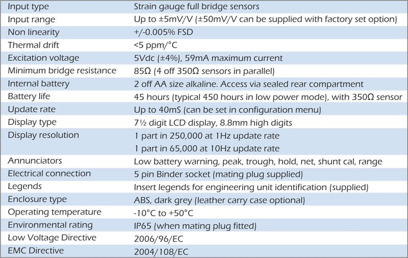
Specification

|
| |
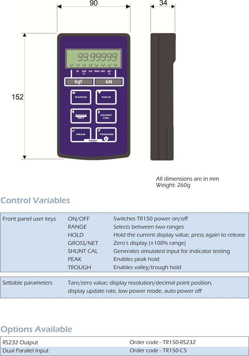
Dimensions

|
| |
Options
 Leather effect carry case Leather effect carry case TEDS compatible TEDS compatible
|
| |
Applications
 Portable load cell systems Portable load cell systems Shackle load cell display Shackle load cell display Link load cell display Link load cell display Hire fleet load cell display Hire fleet load cell display Portable calibration systems Portable calibration systems
|
| |
| |
 |
TR200 Battery Powered Strain Gauge Handheld Indicator
|
|
|
|
|
|
► Powered by internal battery.
► Handheld and portable.
► Environmentally sealed to IP65.
► 4½ digit LCD display, with battery low warning indication.
► Flush mounted push buttons
► Microprocessor based, allowing single pass calibration facility.
► Wide range of options available, including; Intelligent Input, Serial Output, Analogue Outputs, Trips and Data Logging
The TR200 indicator is a completely portable, 4½ digit precision instrument that is ideally suited for use in the harshest of environments or in the laboratory. It is designed to accept the signal from any strain gauge based sensor, with an output sensitivity of up to ±60mV/V. The menu structure facilitates Auto Calibration, Decimal Point Position setting, Fixed Zero (count-by) setting and Digital Filtering rate. Auto-Zero and Peak/Valley Hold functions are available on the front panel, with single key press operation. The menu options offer the engineer the ability to tailor the instrument to an application. Once set, all the menu keys can be disabled to provide the user with the simplest of indicators ideally matched to their requirements.
The TR200 is able to store the parameters for up to 10 sensors, making it ideal for multi-sensor monitoring; allowing switching from one sensor to another, without the need of any calibration adjustment. System expansions are available to enhance the TR200 capabilities. These include; RS232 output for printing or data log downloading, Intelligent sensor recognition, allowing automatic recall of a sensors parameters when it is plugged in to the TR200. Additional options include; Dual Trip outputs, Voltage and Current outputs and Data Logging. The TR200 is supplied complete with a universal 110/230vac battery charger and carry case.
|
| Back to Top |
|
|
Performance
|
| Input type |
Strain Gauge Full Bridge Sensors |
| Input range |
±0.6mV/V to ±7.5mV/V for full scale (±19999) |
| Accuracy |
±2 digits (±0.01% full scale) |
| Thermal drift |
< 100 ppm/°C |
| Excitation Voltage |
5Vdc (±1%), 59mA maximum |
| Minimum bridge resistance |
85Ω (4off 350Ω sensors in parallel) |
| Internal battery |
6V rechargeable sealed battery |
| Battery life |
40 hours, with 350Ω sensor |
| Update rate |
200mS Peak/Valley Hold capture rate is the same as the display |
|
Indication
|
| Display Type |
4½ digit LCD display, 10mm high digits |
| Display Resolution |
±1 digit |
| Annunciators |
Lo Battery warning within LCD display |
| |
Annunciation for Peak Hold indication |
| Identification |
Electronic serial number, stored for customer support purposes |
|
Control variables
|
| Front panel user keys |
Flush Mounting Keys for-ON Switches TR200 power on
OFF Switches TR200 power off
ZERO Zero’s display (±100% range)
CALIBRATE Shunts 100kΩ resistor across bridge (for cal check)
MENU, SELECT, INCREMENT & ACCEPT keys are used to initially set up the TR200 and can be locked to prevent tampering.
Least Significant Digit (count by 1, 5 or 10) |
| Parameters |
Digital Filtering (updates 0.2, 0.8, 1.6 & 3.6 sec)Settable Zero Tracking Enable (active, tracks ±3 LSD)
Decimal Point Position
Front Panel Key Locking |
|
Mechanical
|
| Electrical connection |
5 pin Binder socket (mating plug supplied) |
| Weight |
600 grams |
| Legends |
Self adhesive labels for engineering unit identification |
|
Environmental
|
| Operating Temperature |
-10°C to +50°C |
| Environmental Rating |
IP65 (when mating half connected) |
| Enclosure Type |
ABS, robust yellow case, supplied in separate transit carry case |
|
| Back to Top |
|
 |
| Back to Top |
|
Click here to download - TR200 Datasheet
Click here to download - TR200 Instruction Manual |
|
| The TR200 can be supplied calibrated as a system with any of LCM Systems products. If ordered with any sensor, this calibration will be performed, with traceability to UK National Standards at no extra cost. |
| Back to Top |
|
|
The options detailed below are standard options, which are readily available. They are internally fitted to the TR200. The options can either be fitted singularly or combined to expand the TR200 further. LCM Systems have produced a large number of variants of the TR200 and welcome enquiries for the more unusual or specialist applications.
Logic Input Order code L
This option is a logic input, which allows intelligent recognition of a sensor. The option introduces an extra 12-pin Binder style connector. By linking 5 pins in the correct sequence (details are provided in the manual) on each sensor connected, the TR200 will automatically recognise which sensor is connected. The TR200 has the capability of storing the calibration data for up to 10 sensors. When connected the TR200 will automatically recall all the parameters set for that sensor, including; span and zero settings (the display scaling information), filter settings, decimal point position and if any output options are included, it will also recall these parameters. This option can be further enhanced with an external switching box, which we can also supply. This allows you to connect all the sensors into the switching box, and simply select the sensor that you want to monitor. The setting of these parameters can be locked out after setting up, to prevent tampering.
Serial input Order code R
This option provides an RS232 output. The output continuously flows when the TR200 is powered on, by default. There is also an option, which needs to be specified at time of ordering, which enables the data output to be stopped and started manually through the front panel controls of the TR200. The data stream is 2400 baud, 8 data bits, no parity, 1 stop bit. The data output is the display value, with decimal point positioning. The string terminator is CHR$ (13). A simple software program is available, for customer support purposes and is available on request. The output is provided via a 12-pin Binder style connector.
Voltage output Order code V
The voltage output option gives an analogue output range of ±5 volts for display readings of ±5000, ±10000, ±15000 or ±20000. These ranges are easily scaled using the front panel keys, via the simple menu structure. The setting of these parameters can be locked out after setting up, to prevent tampering. The integrity of the output is protected by the TR200 battery management system, which ensures that the battery level does not drop to a level that affects the voltage output. The output is provided via a 8-pin Binder style connector.
Current output Order code I
The current output option gives an analogue output range of 4-20mA (driving into a maximum of 250Ω) for display readings of ±10000, ±20000, 0-10000 or 0-20000. These ranges are easily scaled using the front panel keys, via the simple menu structure. The setting of these parameters can be locked out after setting up, to prevent tampering. The integrity of the output is protected by the TR200 battery management system, which ensures that the battery level does not drop to a level that affects the current output. The output is provided via a 8-pin Binder style connector.
Dual trip output Order code T
This option allows the setting of two independent trip levels. The trip values are entered using the front panel keys of the TR200, using the display to enter the trip value in real display units. The trip energises when the displayed value exceeds the set trip level value. The two relay outputs supply SPCO contacts rated at 1amp at 240vac. The output is provided via a 8-pin Binder style connector.
Data logging Order code DL
The data logging option allows for up to 4063 single samples to be stored or, dependant on the sample interval selected (which can be between 0.2 seconds and 52 seconds, 0.2 second steps), over 115 hours of data can be collected and stored. The instrument can be configured to continually log data according to the interval selected, or manually log upon demand (using front panel key press). Each sample stores a user definable test number, the interval between samples, the selected channel number and the displayed reading. All this data can be downloaded via an RS232 serial port, which is supplied with this option.
|
|
| Back to Top |
|
► Multi-channel load cell systems
► Fleet hire load cells
► Portable force measurement |
| |
| |
 |
| |
Amplifiers and Conditioners
LCM Systems offer a wide range of load cell amplifiers and conditioners for load cell, sensor and general process applications. We specialise in supplying high performance electronic products that offer high accuracy, performance and speed. Our range of load cell amplifiers and conditioners includes simple internal amplifiers, wireless telemetry systems, strain gauge digitisers and USB conditioning modules.
|
| |
|
|
| |
|
|
| |
|
|
| |
| |
 |
| |
ATEX Tension & Compression Load Cells
Load cells operating in areas where explosive atmospheres are present are required to meet stringent criteria and must be designed in such a way that there is no possibility that they could become a source of ignition. LCM Systems are a market leader in the design and manufacture of ATEX/IECEx load cells for weighing in hazardous areas, having developed a range of load cells specifically designed for use in Zones 1 and 2.
From load cells rated to 2 tonnes to over 1000 tonnes, we can supply many different ranges and sizes, with associated instrumentation to provide a complete package where required.
|
| |
|
|
| |
| |
|