|
| |
PMD-PROCESS Voltage and Current Input Panel Mounting Display
|
| |
|
|
| |
Description
The PMD-PROCESS is a panel mounting display for use with most industry standard voltage & current analogue process signals.
This series of display offers very simple operation and configuration.
The PMD-PROCESS does not use a menu system to configure and calibrate the display, making installation and commissioning very straightforward.
To simplify commissioning even further, the product instruction manual provides step by step pictorial details for each function that you may want to configure, saving time searching through an overly complex manual trying to find that one parameter that you wish to change.
Options valuable for the PMD-PROCESS include:-
 Input options available include 0-10v, 0-5v, 1-5v, 0-10mA, 0-20mA and 4-20mA Input options available include 0-10v, 0-5v, 1-5v, 0-10mA, 0-20mA and 4-20mA
Power supply options available include 95-265vac, 11-30vdc and 48vac.
Output options available include 4-20mA, 0-10v, ±10v, 2 relay alarms, 4 relay alarms, RS232 or RS485.
The main application for the PMD-PROCESS is for simple crane weighing applications, hoist and winch monitoring, as well as many other force measurement applications. It can be connected to any of LCM Systems load cell products, with integrally mounted amplifiers.
Different input signals are available including Serial input, load cell/strain gauge bridge input.
|
| |
Features
- 14.2mm high red LED display
- AC or DC powered versions
- All option boards are pluggable and can be retro-fitted
- IP65 sealed (option for IP67 sealing)
- Menu free setup and calibration
- Panel mounted
- Voltage and current input
- Wide selection of outputs
|
| |
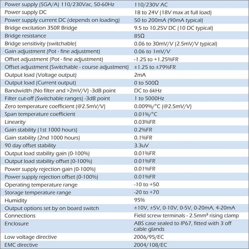
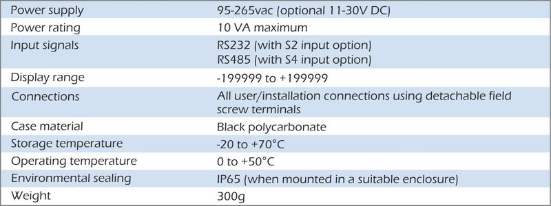
Specification

|
| |
Dimensions
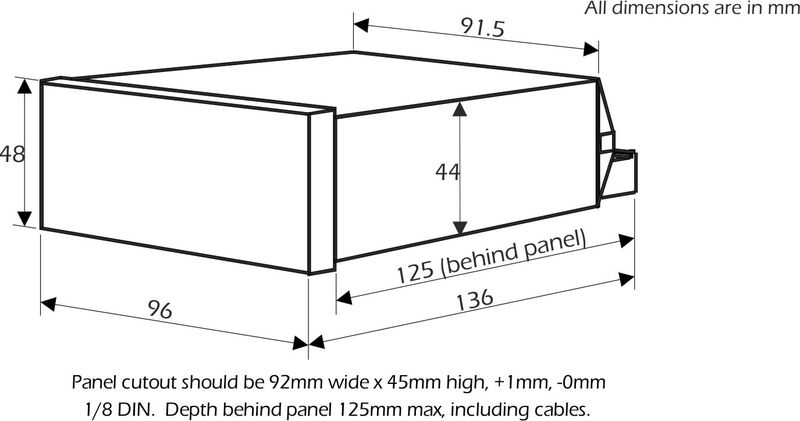
|
| |
Options
- Cover (part number SPC4 for increased sealing to IP67)
- Power supply options: 95-265vac and 11-30vdc
- Input options: 0-10V, 0-5V, 0-10mA, 0-20mA and 4-20mA
- Output options: 4-20mA, 0-10V, +/- 10V, 2 relay alarms, 4 relay alarms, RS232, RS485 or Modbus RTU ASCII
|
| |
Applications
- Vessel weighing
- Winch monitoring
- Crane weighing
- Module weighing
- General force measurement
|
| |
| |
 |
| |
PMD-SERIAL RS232 & RS485 Input Panel Mounting Slave Display
|
| |
|
|
| |
Description
The PMD-SERIAL is a panel mounting display which can be connected to a RS232 or RS485 ASCII serial bus, primarily for use as a remote slave display.
This series of display offers very simple operation and configuration. The PMD-SERIAL does not use a menu system to configure and calibrate the display, making installation and commissioning very straightforward.
To simplify commissioning even further, the product instruction manual provides step by step pictorial details for each function that you may want to configure, saving time searching through an overly complex manual trying to find that one parameter that you wish to change.
Options valuable for the PMD-SERIAL include:-
Input options available include RS232 and RS485/RS422
Power supply options available include 95-265vac, 11-30vdc and 48vac.
Output options available include 4-20mA, 0-10v, ±10v, 2 relay alarms, 4 relay alarms, RS232 or RS485.
The main application for the PMD-SERIAL is for simple crane weighing applications, hoist and winch monitoring, as well as many other force measurement applications.
Different input signals are available including Load Cell/Strain Gauge bridge input (see PMD-STRAIN), process input (see PMD-PROCESS). LCM Systems engineers will be pleased to discuss your specific application requirements with you. They will be able to advise on the correct product selection, options required and advise on suitable sensors, where required.
|
| |
Features
- 14.2mm high red LED display
- AC or DC powered versions
- All option boards are pluggable and can be retro-fitted
- IP65 sealed (option for IP67 sealing)
- Menu free setup and calibration
- Panel mounted
- RS232 and RS485 input
- Wide selection of outputs
|
| |
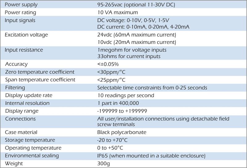
Specification

|
| |
Dimensions

|
| |
Options
- Cover (part number SPC4 for increase sealing to IP67)
- Power supply options: 95-265vac and 11-30vdc
- Input options: RS232 and RS485/RS422
- Output options: 4-20mA, 0-10V, +/- 10V, 2 relay alarms, 4 relay alarms, RS232, RS485 or Modbus RTU ASCII
|
| |
Applications
- Vessel weighing
- Winch monitoring
- Crane weighing
- Module weighing
- General force measurement
|
| |
| |
 |
| |
PMD-STRAIN Load Cell and Strain Gauge Input Panel Mounting Display
|
| |
|
|
| |
Description
The PMD-STRAIN is a panel mounting display for use with strain gauge bridge based sensors,; including load cells, load pins etc.
This series of display offers very simple operation and configuration.
The PMD-STRAIN does not use a menu system to configure and calibrate the display, making installation and commissioning very straightforward.
To simplify commissioning even further, the product instruction manual provides step by step pictorial details for each function that you may want to configure, saving time searching through an overly complex manual trying to find that one parameter that you wish to change.
Options valuable for the PMD-STRAIN include:-
Power supply options available include 95-265vac, 11-30vdc and 48vac.
Output options available include 4-20mA, 0-10v, ±10v, 2 relay alarms, 4 relay alarms, RS232 or RS485.
The main application for the PMD-STRAIN is for simple crane weighing applications, hoist and winch monitoring, as well as many other force measurement applications.
Different input signals are available including Serial input (see PMD-SERIAL), process input (see PMD-PROCESS).
LCM Systems engineers will be pleased to discuss your specific application requirements with you. They will be able to advise on the correct product selection, options required and advise on suitable sensors, where required.
|
| |
Features
- 14.2mm high red LED display
- AC or DC powered versions
- All option boards are pluggable and can be retro-fitted
- IP65 sealed (option for IP67 sealing)
- Load cell input
- Menu free setup and calibration
- Panel mounted
- Wide selection of outputs
|
| |
Specification
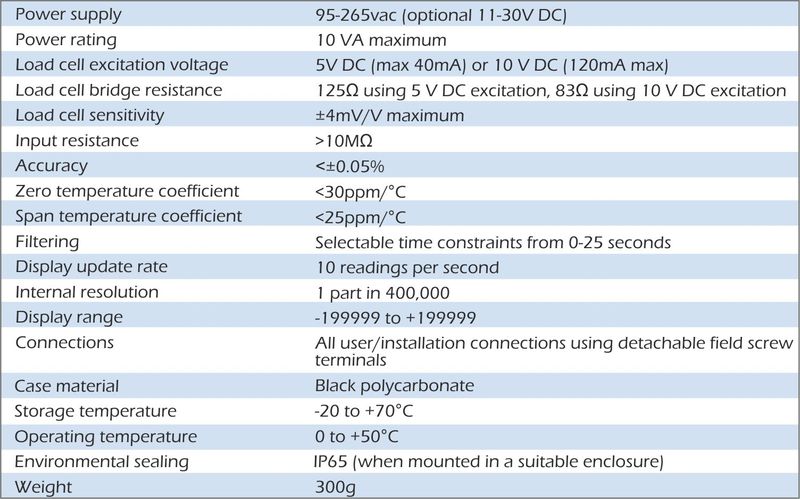

|
| |
Dimensions

|
| |
Options
- Cover (part number SPC4 for increase sealing to IP67)
- Power supply options: 95-265vac and 11-30vdc
- Output options: 4-20mA, 0-10V, +/- 10V, 2 relay alarms, 4 relay alarms, RS232, RS485 or Modbus RTU ASCII
|
| |
Applications
- Vessel weighing
- Winch monitoring
- Crane weighing
- Module weighing
- General force measurement
|
| |
| |
RCA15 Rack Mounted Intelligent Strain Gauge Amplifier
|
|
|

Features | Specification | Dimensions | Downloads | Suggested Instrumentation | Options | Applications
-
Selectable Strain Gauge sensitivity from 0.5 to 200mV/V
-
Simple one pass auto calibration
-
Auto Tare
-
Isolated analogue outputs 4-20mA and 0-10V outputs
-
10V @ 1.4A excitation for each rack
-
High accuracy/low drift
-
3U 19" rack frame
-
10 year data retention
-
Digital programming, calibration & display
-
Optional Communications for each channel include RS485, RS232
-
Optional 2 setpoints/relays for each channel
The intelligent Strain Gauge amplifier offers both 4 to 20mA and 0 to 10 volt analogue outputs, from any standard Strain Gauge input. Ease of calibration and setting of the analogue output range, make the modules extremely user friendly; being set up by a simple hand held plug in programmer or a built in programmer/display.
Auto Tare and Peak Hold (if set) on the analogue output are operated via volt free contact closures.
Output options include:-
Relay Set Points (Programmed in engineering units; with In Flight compensation and Hysteresis settings available for control or alarm purposes)
Communications:-
To read any value, change set points or any other parameter via:
RS232/RS485 (RC3) - Formats MANTRABUS, ASCII, MODBUS RTU
Printer Activated by a contact closure, displays the current live value, with header message, engineering units, auto incrementing batch number and a real time if required.
|
|
Back to the To
|
Input Details
|
|
The input is suitable for any full wheatstone bridge sensor and transducer excitation voltage 9.6 volts 1.0A (common to all channels).
|
|
Compensation
|
by ± sense wires for cable connection, voltage drops and any variation in the excitation supply.
|
|
Load cell sensitivity
|
is preset via DIL switches to 0.5, 0.8, 1.0 1.25, 1.5, 2.0, 2.5, 3.5, 5,10, 20, 50, 100 or 200mV/V.
|
|
Initial offset
|
≤±0.15mV (15µV/V) which is cancelled during auto calibration.
|
|
Speed
|
10 readings per second with a digital filter to reduce speed.
|
|
Accuracy
|
is 90 days ±0.08% of reading, ±0.05% FSD (typically)
|
|
Drift
|
is ±0.002% per degree C @ 2.5mV/V (typically)
|
|
Resolution
|
15 bit (4.5 digits)
|
|
Contact inputs
|
Available for auto tare, print and peak hold reset and are volt free
|
Rack Mounted Load Cell Amplifiers
|
|
Two versions are available to mount in the standard 19” rack
|
|
Version 1 (RL1)
|
comprises an amplifier which is programmed via a hand held, plug in programmer. This version allows for the fitting of the 12 amplifiers.
|
|
Version 2 (RL2)
|
comprises an amplifier which has a front panel mounted LCD display; program buttons are accessed through 2.2mm apertures in the panel. This version allows for the fitting of 8 amplifiers.
|
Analogue Outputs
|
|
Drive
|
4-20mA up to 1Kohm and 0-10 volts up to 2mA.
|
|
Accuracy
|
4-20mA ±0.15% of range (typically) 0-10V ±2% before calibration
|
|
Resolution
|
13 bit (Settling time 0.25 secs to 1% of step change)
|
|
Isolation
|
±130V RMS or DC max to analogue input or any other port.
|
Data Retention/Protection
|
|
Retention
|
10 years for set up values, minimum of 100,000 write cycle
|
|
|
Protection of data and function(s) Watchdog timer giving repeat auto resets.
|
|
|
Impending power detection and hold off.
|
|
|
Keypad security and time out.
|
Options Available
|
|
2 set points
|
Output through 5A, 230V ac SPCO relays (volt free contacts with latching and inversion options
|
|
Communications Port
|
20mA loop - enabling up to 254 to be multi dropped to 1 x RS232 via IF25 interface
|
|
|
RS485 - enabling up to 32 units to be multi dropped (isolated)
|
|
|
RS232 - for 1 to 1 connection and standard printer drive (isolated)
|
|
|
Baud Rates - 300, 600, 1200, 2400, 4800, 9600 (19200 MANTRABUS only)
|
CE & Environmental
|
|
Storage temperature
|
-20 to +70ºC
|
|
Operating temperature
|
-10 to 50°C
|
|
Relative humidity
|
95% maximum non condensing
|
|
Safety/Low Voltage Directive
|
2006/95/EC
|
|
EMC Directive
|
2004/108/EC
|
|
|
Back to the Top
|
|

|
|
Back to the Top
|
|
Click here to download - RCA15 Datasheet
Click here to download - RCA15 Instruction Manual
|
|
Back to the Top
|
|
|
|
Back to the To
|
|
|
|
| |
| |
|