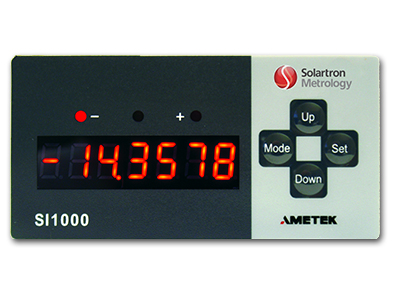
The SI 1000 Series are a cost effective yet versatile panel mount, single channel display series specifically designed for use with Solartron's Analogue Gauging Probes and Displacement Sensor.
The SI 1300 is designed for use with DC/DC sensors, providing a voltage and current input.
Instruments for Analogue Sensors
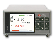
Digital Displays for analogue sensors are available in a wide range allowing for simple to complex applications. All displays feature serial communication and digital I/O to allow PLC, PC and footswitches to operate the instruments.
Dual channel TFT display. Serial, Analogue and Digital outputs. LVDT, Half Bridge, V/I inputs.
GEMCO Series - S955 - Specifications
Measurement
Measurement Range
100mm to 4572mm (4” to 180”)
Accuracy
+/-0.05% of FRO or 1.27mm whichever is greater
Non-linearity
+/-0.01% of FRO or 0.71mm whichever is greater
Resolution
.035mm
Repeatability
+/- 0.01% of FRO or +/-.035mm whichever is greater
Hysteresis
±0.01% of FRO
Dead Band
38.1mm (1.50”) standard
Null Zone
76.2mm (3.00”) standard
Mechanical
Body Length
Hex Base
Thread
LED
Diagnostic Tri-Colour LED
Electrical Interface
Input Voltage
10-30 VDC
Current Draw
100mA Maximum
Connector
4 Pin 12mm Euro micro
Update Time
100=mm to ≤ 1270mm = 1ms
1271mm to ≤ 2540mm = 2ms
2541mm to ≤ 3810mm = 3ms
3811mm to ≤ 4572mm = 4ms
LED
Diagnostic Tri-Colour LED
Green = Power is applied and magnet is present Red = Fault, magnet is in the Dead Zone or lost Yellow = Out of the active programmed range
Zero & Span Adjustability
Factory set at Null & Dead Band locations, Field re-settable at any location within active stroke programmed range
Output
V0 = 0-10 VDC
V1 = 10-0 VDC
V2 = -10 to 10 VDC
V3 = 10 to -10 VDC
V4 = 0 to 5 VDC
V5 = 5 to 0 VDC
V6 = -5 to 5 VDC
V7 = 5 to -5 VDC
C4 = 4 to 20Ma
C4 = 20 to 4mA
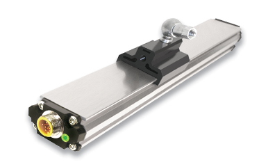
The S955 Brik Linear Displacement Transducer is an economical solution for monitoring continuous position. It is desgined for OEM wishing to opt for a cost effective alternative to limit switches, proximity sensors or linear potentiometers. The streamlined anodized aluminium extrusion houses the sensing element and the electronics. The position is determined by the magnet which is linearly guided over the sensing element.
For more information, please consult the Datasheet.
< 0.01% or ±0.127mm (±0.005”) whichever is greater,
(±0.051mm or ±0.002” Typical)
Resolution
Internal: 1.524μm (0.00006”)
Output: 16-Bit
Repeatability
Equal to resolution
Hysteresis
25.4μm (0.001”)
Dead Band
63.5mm63.5mm (2.50”) standard
Null Zone
50.8mm (2.00”) standard
Mechanical
Body Length
81.28mm (3.2”)
Hex Base
44.45mm (1¾”) diameter
Thread
M18x1.5
LED
Diagnostic Tri-Colour LED
Electrical Interface
Input Voltage
7 to 30 VDC
Current Draw
1 watt typical, 40mA at 24VDC
Connector
5 Pin 12mm Euro micro, integral cable assembly, 6 Pin
or 8 Pin DIN
Update Time
L ≤ 51mm = 0.5ms
51mm to ≤ 305mm = 1ms
306mm to ≤ 763mm = 2ms
763mm to ≤ 1270mm = 3ms
1271mm to ≤ 2540mm = 4ms
2541mm to ≤ 3810mm = 5ms
3811mm to ≤ 4572mm = 6ms
4573mm to ≤ 6350mm = 7ms
6351mm to ≤ 7620mm = 8ms
LED
Diagnostic Tri-Colour LED
Green = Power is applied and magnet is present
Red = Fault, magnet is in the Dead Zone or lost
Yellow = Out of the active programmed range
Zero & Span Adjustability
Factory set at Null & Dead Band locations,
Field re-settable at any location within active stroke
Output
V0 = 0-10 VDC
V1 = 10-0 VDC
V2 = -10 to 10 VDC
V3 = 10 to -10 VDC
V4 = 0 to 5 VDC
V5 = 5 to 0 VDC
V6 = -5 to 5 VDC
V7 = 5 to -5 VDC
C4 = 4 to 20Ma
C4 = 20 to 4mA
Environmental
Storage Temperature
40°C to 105°C (-40° to 221° F)
Operating Temperature
Head
Guide Tube
-40°C to 85°C (-40° to 185° F)
-40°C to 105°C (-40° to 221° F)
Enclosure
IP68, IEC 600529
Vibration
30Gs (lab tested)
IEC 60068-2-6
Shock
1000Gs (lab tested)
IEC 60068-2-27
Guide Tube Pressure
345 bar (5000 psi) continuous
689 bar (10000 psi) spike