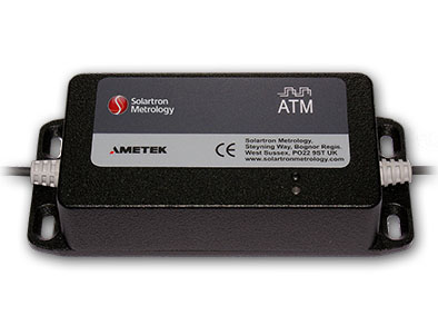
TTL/RS422 Differential Quadrature is one of the most commonly used methods of communication between Linear Displacement Transducers and Control or Data Acquisition systems. Its simplicity of interfacing with programmable systems also makes it one of the most cost effective. The Solartron ATM module is coupled to Solartron Absolute Position Transducers and converts the output to a digital signal. The transducer signal conditioning is designed such that unlike incremental TTL systems, it will not suffer from "over speeding" or lose position during a power down.
1For other input voltages, please contact Solartron.
2For other output frequencies, please contact Solartron.
Signal Input (Sensor Sensitivity Range)
Input Range
Up too 2.5 Vrms
Input Load Resistance (kΩ)
100
Signal Output
Voltage Output (VDC)
Up to ± 10
Maximum Current Output (mA)
11
Output Ripple
< 40 mVrms
Output Offset
100%
Temperature Coefficient Gain
< 0.03% FRO/°C
Temperature Coefficient Offset
< 0.025% FRO/°C
Warm Up Time
15 Minutes (recommended)
Linearity
< 0.1% FRO
Bandwidth-3db (Hz)
250 typical
Environmental
Operating Temperature Range (°C)
0 to +70
Storage Temperature Range (°C)
-20 to +85
IP Rating
IP 40
IP 65
Mechanical and Connections
Connections
Solder Pad or Factory Fit
Factory Fit only
Enclosure Dimensions without Connectors (mm)
98.5 x 30.5 x 13.0
73.0 x 20.6
Weight (g)
30
75
Material
ABS
400 Series Stainless Steel
Cable Lengths
All specification limits assume a nominal 3 m cable length between transducer and BICM. The BICM can be mounted up to 10 m from the sensor, but this may result in reduced performance. Not all transducers can cope with long cable lengths.
(Cable from the BICM to the processing or display unit should be limited to 100 m).
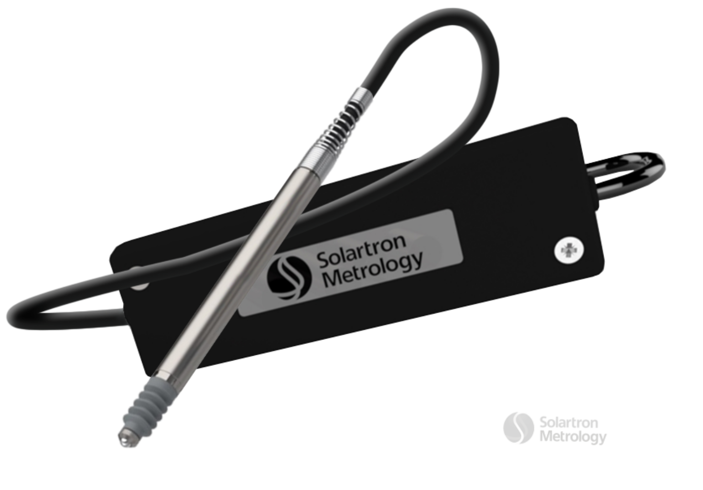
Analogue probes can be ordered with an In-line Conditioning Module that is calibrated at the Solartron factory, providing ease of setup.
The BICM provides a simple low cost in line conditioning unit. This is ideal when the transducer set up is unlikly to require adjustment. For use inharsh environments a sealed version is available.
DRC Range Inline Analogue Conditioner - Specification
DRC Inline Conditioner
Power Requirements
Bipolar Supply
Voltage (VDC)
10 to 30
Current Range
160 mA @ 10 V to 70 mA @ 30 V
Sensor Excitation
Primary Voltage (Vrms)
3 nominal
Primary Frequency (kHz)
5, 10 or 13 (Link Selectable)
Signal Input
Input Range (mV)
55 to 5000 (LVDT Full Range)
Input Load Resistance (kΩ)
100, 2
Options
(See note1)
1No inputs are offered. As connection is by screw terminal, additional internal configuration methods are not required.
By changing connections and use of external components, the user can perform:


 DC signal conditioning mounted in line on cable