 |
||||||||||||||||||||||||||||||||||||||||||||||||||||||||||||||||||||||||||||||||||||||||||||||||
|
Calibration Gauge/Gauge Pin Unit/Fixture Guide for Surface Variation Detectors
|
||||||||||||||||||||||||||||||||||||||||||||||||||||||||||||||||||||||||||||||||||||||||||||||||
| Calibration Gauge | ||||||||||||||||||||||||||||||||||||||||||||||||||||||||||||||||||||||||||||||||||||||||||||||||
|
||||||||||||||||||||||||||||||||||||||||||||||||||||||||||||||||||||||||||||||||||||||||||||||||
|
[ *] Φ0.5mm or less can be made for Φ0.1mm.
|
||||||||||||||||||||||||||||||||||||||||||||||||||||||||||||||||||||||||||||||||||||||||||||||||
| Gauge pin Unit Fixture and Gauge pin Unit | ||||||||||||||||||||||||||||||||||||||||||||||||||||||||||||||||||||||||||||||||||||||||||||||||
|
||||||||||||||||||||||||||||||||||||||||||||||||||||||||||||||||||||||||||||||||||||||||||||||||
|
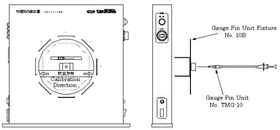
Example of calibration method (TM-3004W)
The detector is provided a calibration before the delivery. However, if another calibration is required in order to assume the detecting sensitivity at the examination, you have to follow the method mentioned below to make it correctly, using a calibration gauge pin unit. (Calibration Gauge Pin Unit No.TMG-10 and Gauge Pin Unit Fixture No.10B are the optioned items).
Calibration procedure for #1 axis. 1. Place the Gauge Pin Unit Fixture into the Detector with "arrow" mark setting to the #1 axis. (ref. Fig.).
2. Set Variation Detecting Level Setter at "1.00". 4. While repeating the insertion, adjust #1 axis Gain Adjustment VR at the minimum level where the variation detection alarm lamp turns on at the time when the Gauge Pin Unit is inserted. Variation Detection Alarm Lamp turns on at the time when the point of Gauge Pin Unit is inserted. *The Variation Detection Alarm Lamp would turn on occasionally when the point of Gauge Pin Unit is pulled out, but this phenomenon shall be ignored. *While repeating the insertion, take interval of 3 seconds after Variation Detection Alarm Lamp turns off. *Sensitivity comes up by turning Gain Adjustment VR clockwise and comes down by turning it anti-clockwise.
5. Set Variation Detecting Level Setter at "1.03". 6. Repeat the insertion and adjust #1 axis Gain Adjustment VR at the level where Variation Detection Alarm Lamp does not turn on at the time when the point of Gauge Pin Unit is inserted. 7. Repeat the procedure (2) through (6). And, the calibration has been finished properly if Variation Detection Alarm Lamp turns on at the level "1.00" and turns off at the level "1.03". Follow the above procedure to calibrate other axes, placing Gauge Pin Unit Fixture into the Detector with "arrow" mark setting to the axis to be calibrated. |
||||||||||||||||||||||||||||||||||||||||||||||||||||||||||||||||||||||||||||||||||||||||||||||||
 |
||||||||||||||||||||||||||||||||||||||||||||||||||||||||||||||||||||||||||||||||||||||||||||||||