Inductive Technology


inductive1


Principle of Operation
 
An LVDT (linear variable differential transformer) inductive displacement sensor is constructed using a static transformer primary winding and two secondary windings. The windings are formed on a hollow bobbin through which a magnetic core can travel. The core provides a path for linking the magnetic flux generated in the primary coil, when this is energised with an AC signal, to the secondary coils. The position of the core in the bobbin controls how much flux is coupled to each of the secondary coils.


inductive2

 
The secondary coils A and B are connected in series opposition so that the two voltages VA and VB have opposite phase and the transducer output is VA-VB. If the core is in the central position then voltages of equal magnitude, but opposite phase are induced in each secondary and the resulting output is zero. When the core is moved in one direction, the voltage in one secondary increases and that in the other decreases. The net effect is an output that is proportional to the position of the core. Knowledge of the magnitude and phase of the output with respect to the excitation signal allows one to deduce the position of the core with respect to the zero position.


inductive3

 
The output of an LVDT is a linear function of the displacement over its calibrated range. Beyond this range the output becomes increasingly non linear. Measurement range is defined as ± distance from the transducer zero or null position.
 

Inductive Technology


LVDT and Half Bridge


LVDT and Half Bridge
 
An LVDT and a Half Bridge are two alternative approaches to the coil format and are described in this section.


Conventional Half Bridge

 
Conventional Half Bridge
 
The half bridge transducer forms half of a Wheatstone bridge circuit, which enables change from null to be easily detected. The other half of the bridge is contained within the conditioning electronics. When the core is in the null position the bridge is balanced and the output is zero. As the core moves the relative inductance of the bridge changes producing an output.


Conventional LVDT

 
Conventional LVDT
 
If the core is in the central position then voltages of equal magnitude, but opposite phase are induced in each secondary and the resulting output is zero. When the core is moved in one direction, the voltage in one secondary increases and that in the other decreases. The net effect is an output that is proportional to the position of the core.


Solartron Half Bridge and LVDT

 
Solartron Half Bridge and LVDT
 
Solartron has continually developed precision bobbin mouldings including multi chamber bobbins which in conjunction with skilled design of the coils ensure excellent stability and linearity.
 

Gauging Probe - Robust Design - Finest Quality

Contact Gauge Probe

Contact gauge Probes very often provide the only cost effective solution for a wide range of measuring and positioning applications in diverse industries.


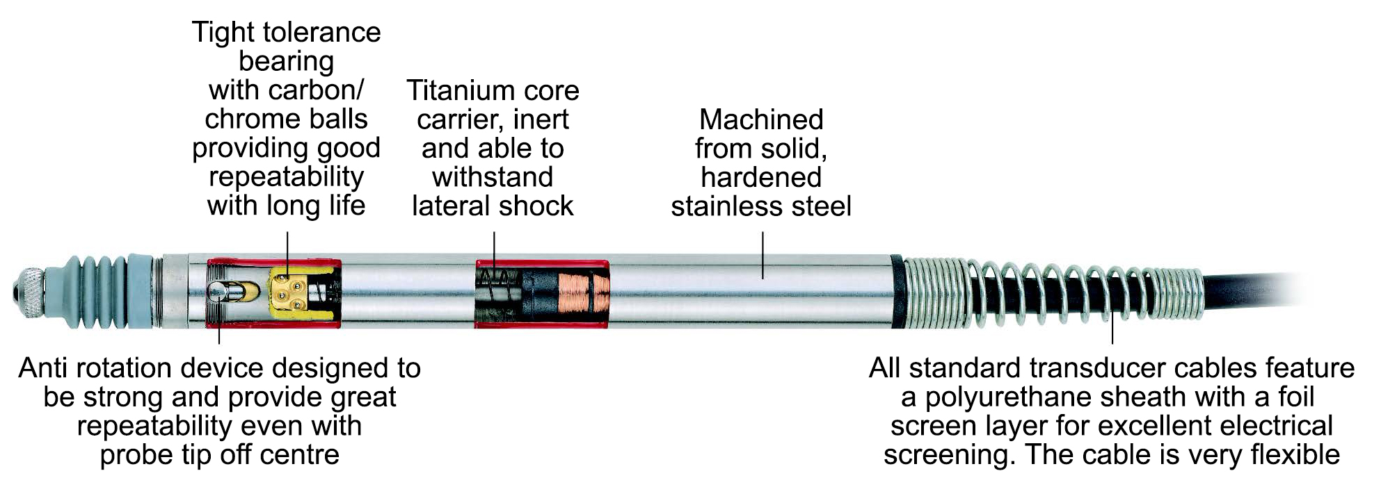
As with all mechanical transducers, life is of paramount importance. It is not too difficult to produce a gauge probe that works well when new, but considerably more difficult to produce a probe that maintains its performance throughout a long working life.


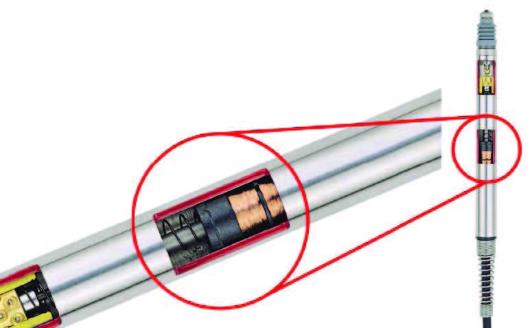
It requires close attention to detail in design and manufacture as well as investment in state of the art machines to produce precision bearings which are the heart of a gauge probe.


Solartron Metrology has complete control over all aspects of the design and manufacture of its sensors. Whether the application is in the laboratory or in manufacturing our extensive range of transducers will most likely provide a solution. If nothing seems to meet your need we will always consider customised products.


Please register here in order to access the download page.
Name: *
Email address: *
Company Name: *
Designation: *
Contact No: *
 
  * Please filled in the required details.