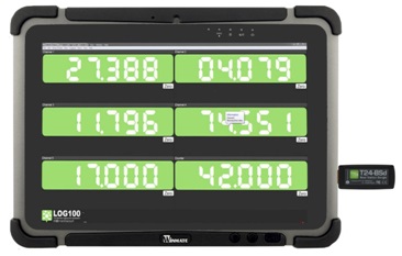
Stage load monitoring and limit alarm


Advantages


Load Shackles

Load Links
 Ranges 3.25tonne to 9.5tonne

 T24-HS-LS hand-held display utilising 2.4GHz License    Free Frequency

 Stainless steel load pin

 Environmentally sealed to IP67

 Simple installation and operation

 Continuous use battery life of 650 hours (with 2.3Ah        batteries)

 Shackle and load pin fully certified

 Transmission range of up to 600 metres clear line of sight

 Supplied with load centralising bobbin

 Many other telemetry configurations available.

 Machinery Directive 2006/42/EC compliant

 Ranges 1 to 300 tonne

 Lightweight Aluminium Construction

 Shackle holes are steel bushed

 Environmentally Sealed to IP67

 License Free 2.4GHz radio

 Can be supplied with various bespoke telemetry and/or    software packages

The TELSHACK-B-JR range of telemetry load shackles are manufactured using the Crosby™ G2130  shackle. Suitable for use in a wide range of lower capacity industrial weighing applications, these load shackles are accurate, reliable and simple to install. They are particularly popular in theatrical applications for measuring the loads on rigging, hoists and stage lifts.


The IP67 rated telemetry housing is manufactured from ABS plastic making it strong yet light, and the telemetry electronics contained within are powered by two AA alkaline batteries. The unit also features an internal antenna for maximum protection from damage. 

The LCM RILL series of wireless link load cells have been designed for lifting and weighing in rugged or harsh environments, being manufactured from high tensile aluminium to minimise weight (has steel bushes to provide added wear protection from shackles etc).


Software


T24LOG100 has been designed to allow the logging and visualisation of up to 100 channels of data from the T24 Wireless Telemetry range of sensor transmitters.


A resizable window displays a table of up to 100 channels of data. Channels can be setup with user defined algorithms that can be used to calculate a multitude of maths functions. For example, a display can show the value from a single T24 transmitter module or the sum of multiple transmitters. Visual displays and audible alarms can indicate under and over range as well as loss in communications, low battery and error reports.

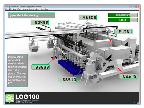
Once the display channels are defined the user can quickly build graphical pages showing the data in a variety of formats including digital display or bars. Up to eight pages can be defined and the pages easily navigated between. A variety of image formats can be imported, including JPG, GIF, PDF and DXF.


T24LOG100 can log on demand, at pre-set intervals, on entering and leaving a pre-set overload and during an overload. It creates a CSV file which can be loaded for analysis into software programs such as Microsoft Excel. JSON format data is also available on demand via the built in web server.


Key Features & Benefits


 Free 100 channel software

 Displays and logs data from up to 100 wireless sensor transmitters from our T24 wireless        range

 Mapping / graphical capabilities

 Centre of Gravity (COG) function

 Webserver offers remote viewing on iPads/tablets/smart phones and also supplies JSON        data on demand

 Create reports for your customers and develop custom projects

 Compatible with Windows XP, Vista, Windows 7, Windows 8 and Windows 10

 Defined algorithms and maths function

 Logging at timed intervals, manual or on overload/underload

 Visual and audible alarms indicates over and under load

 Visual alarm for low batteries and loss in communication

 Zoom in to channel to see data trends and history

 Quick & easy to install

 Export and log data in CSV format

 Centre of Gravity designer and functionality


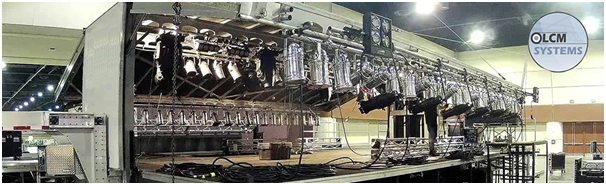
Solution for unpredictable load distribution


Safety for the performers and spectators are very important when considering the design of the truss set up. With tons of sound and lighting equipment hanging from the above, the need for even distribution of load is very important. The monitoring needs to have fast response due to the continuous movements of these audio visual (A/V) equipment.


There are situations whereby, due to the continuous movement of the A/V equipment, there would be uneven load distribution on one of the hoist and may reach its’ overload limit. Conditions may even worsen especially during outdoor set ups which are exposed to wind and snow build up on the roof. These conditions would greatly reduce the overload tolerance of the whole truss set up.


The solution is to identify the load distribution and ensuring safe installations during real-time performances.


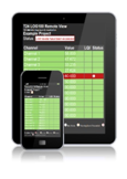
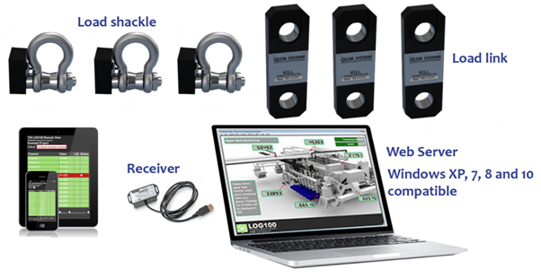
Mobility, Portability, User-Friendly


Product and Technology News

Ports & Terminals

Product Selector

LCM Systems

Application Selector

LCM Systems

Download Catalogue