How it Works
- 1. In this application, the rocket engine is threaded into the LCF series universal load cell.
- 2. The engine mount prevents any side loading on the cell, ensuring the load cell is only receiving axial loads.
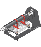
- 3. The load cell assembly is mounted to a fixed test stand securing the engine.
- 4. In line with the base supports, MTA400/MTA600 multi-axis load cells are installed.
- 5. As the engine is operating, thrust is measured with the LCF series load cells.
- 6. Mass flow and Drag(aka “kick”) are captured with MTA400/MTA600 load cells.
- 7. Thrust data can be live streamed and logged for monitoring and later review and comparison against simulated models with USB220 and SENSIT.
- 8. Mass flow data from all 4 multi-axis load cells are captured, streamed and logged with USB220 and SENSIT.
- 9. Each axis of the MTA400/MTA600 is captured with a separate USB220.
- 10. Load cell output can also be amplified via the IAA series for capture by pre-existing DAQs.