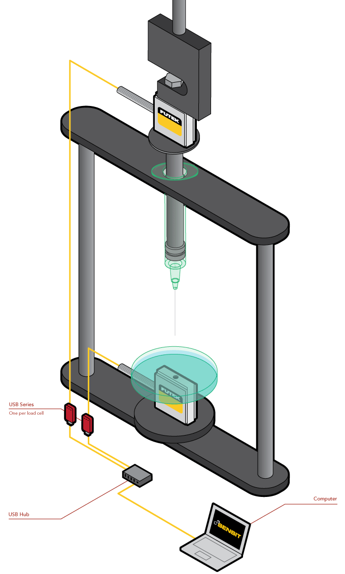
Syringe Test Stand
How it Works
- Mounted to a mechanical lever, one of FUTEK's LSB200 Jr. Miniature S-Beam Load Cells will measure the force applied to the syringe's pump as it dispenses fluid.
- The second LSB200 will monitor the load of fluid emitted from the syringe.
- These two measurements can be streamed and collected through FUTEK's USB Solutions.
- Executing SENSIT™ Test and Measurement Software alongside these USB Solutions allows the inspector to data log these results on two different channels.
- From here, the quality inspector may compare each channel of results to effectively gauge the force of exertion verses the fluid dispensed.
|
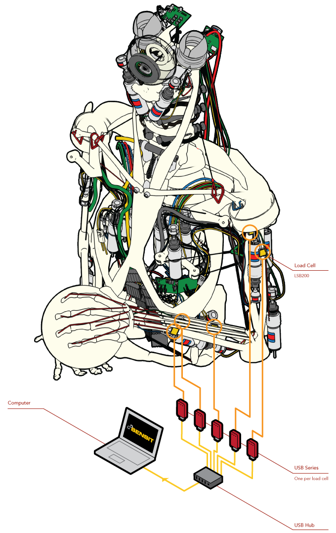
Humanoid Robot Load Cell
How it Works
- In 2012, The Robot Studio decided to replicate human mechanics by developing the most precise and complex mechanism - a humanoid robot.
- While emulating the structure and geometry of human forelimbs, all bones, joints and connective tissue required force monitoring.
- The Robot Studio employed FUTEK's LSB200 Jr. Miniature S-Beam Load Cell to audit the mechanical loads as the humanoid operated.
- Being that size constraints were a challenge, the miniature load cell fit perfectly into the architecture of the design and delivered exact force measurements via USB Solutions.
- These loads were streamed onto a PC and analyzed through FUTEK's SENSIT™ Test and Measurement Software.
|
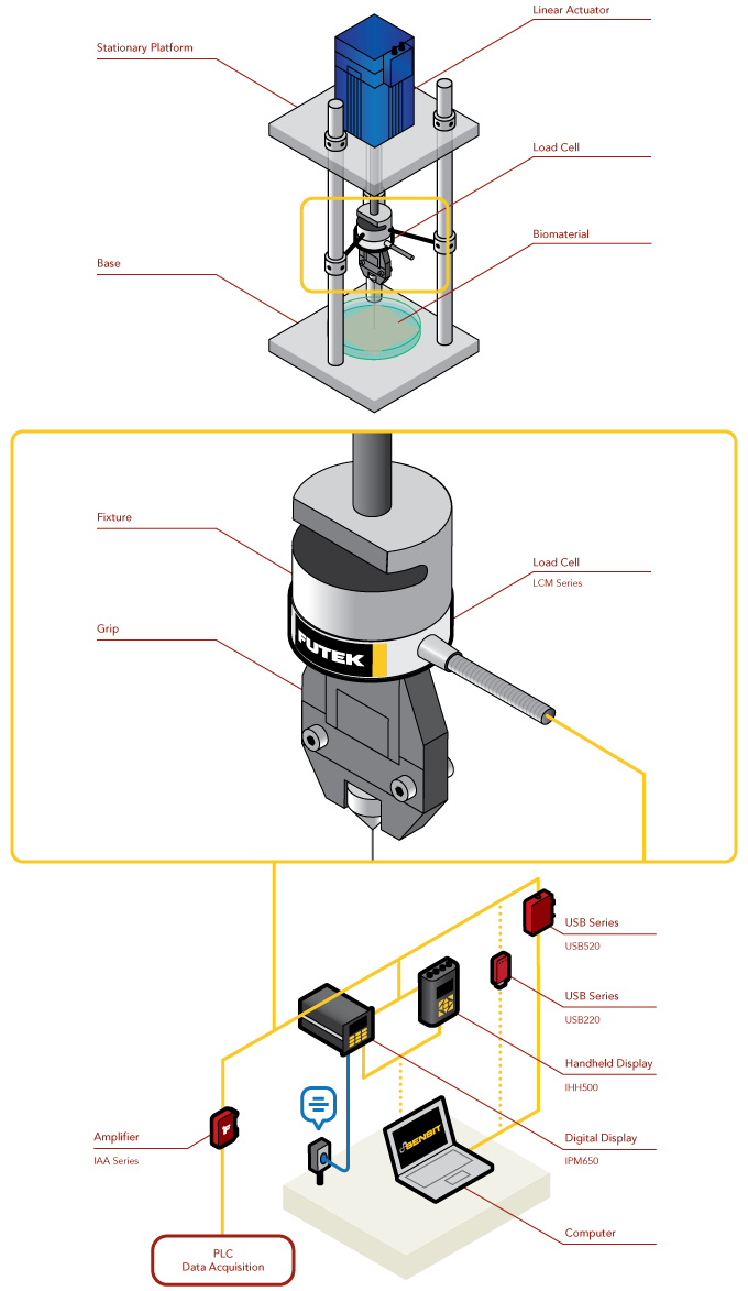
Biomedical Research Testing
How it Works
- Biomedical researchers often work with very sensitive and delicate materials.
- Load cells allow researchers the ability to monitor the force applied to their test specimens.
- In the above application, a Miniature Threaded In Line Load Cell (LCM Series) has been mounted to a linear actuator. As the actuator drives the needle into the biomaterial, load feedback can be shown on either FUTEK’s IHH500 or IPM650 digital displays or streamed through USB onto a PC.
- Pairing the SENSIT™ Test and Measurement Software with any of these instrument options provides the user with the ability to data log and live graph.
|
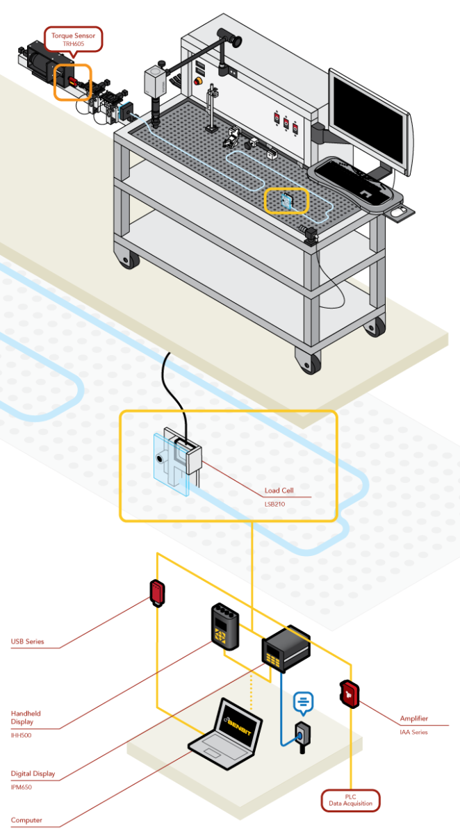
Catheter Track Force Test
How it Works
- The purpose of an interventional device test is to reduce risk to the patient during medical procedures. Medical researchers conduct test with these systems to learn more about their performance features such as trackability.
- Trackability or track force refers to the force required to advance through a tortuous object. Precise measurement modules are needed to accurately record findings of force vs. position.
- The LSB210 is fixed on the test system to quantify the force exerted to advance the catheter through a tortuous anatomy. The LSB210’s overload protection feature provides assurance to researchers in case of accidental overload.
- These force measures can be streamed to a computer utilizing FUTEK's USB Solutions. FUTEK’s USB modules are configured by the ASCII stream along with the DLL which allows users to integrate custom software if needed.
- Once streamed to a computer, that data can then be monitored by FUTEK's SENSIT™ Test and Measurement.
|
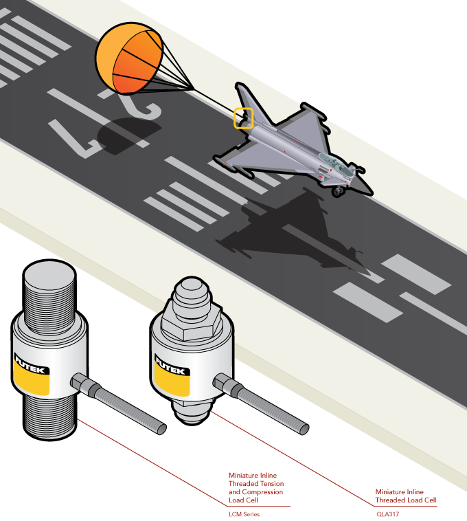
Jet Parachute Deployment
How it Works
- When runway length is tight, military aircrafts deploy parachutes to assist in rapid deceleration.
- These parachutes require extensive precision and endurance (fatigue) testing prior to use.
- Utilizing either standard or customized Miniature Threaded In Line Load Cells in a wire tension measurement application allow quality inspection engineers to audit the tensile forces applied to the parachute cable throughout deployment and use.
- These tensile forces can be read on a number of instruments, including our digital displays (IHH500 or IPM650) or streamed to a PC via our USB Solutions.
|
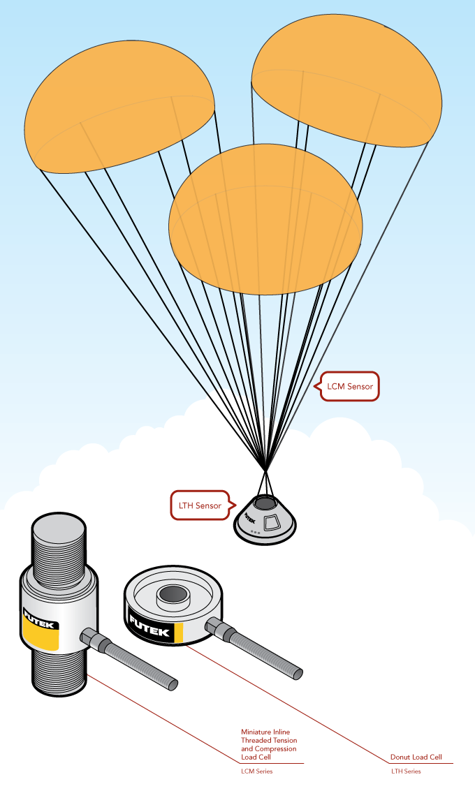
Orion Deployment Mechanism
How it Works
- NASA missions require the highest in quality during auditing phases of their components. The Orion Multi-Purpose Crew Vehicle mission was no different.
- For this application, FUTEK's load cells served as the auditing tool measuring the force of the payload (the Orion capsule) against the cables from the parachute deployment mechanism.
- Two solutions were developed to fit this application's requirements.
- In the first solution, quality assurance engineers could install FUTEK's Miniature Threaded In Line Load Cell between the cables creating a wire tension measurement application.
- The second solution allows these engineers to mount the Donut/Thru Hole Load Cells at the base of the deployment system to measure the immediate and continue force the payload applied to the parachute cables.
- Both solution options provided NASA's test engineers with highly accurate testing data.
|
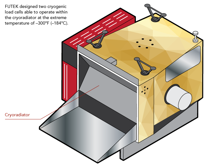
NASA Satellite Load Cells
How it Works
- NASA's Suomi NPP Satellite, in conjunction with the VIIRS instrument, is responsible for new advances in weather and environmental monitoring.
- FUTEK specifically worked with Raytheon to develop two cryogenic load cells to operate in orbit within the VIIRS instrument.
- The application requirements called for dual bridge, cryogenic temperatures up to -300°F (-184°C), vacuum rated, shock and vibration tested, and able to operate post launch.
|
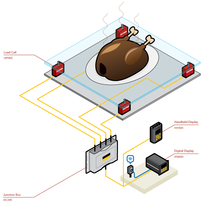
Precision "Feast" Measurement Scale/Platform
How it Works
- Precision scales require high-accuracy, compression load cells.
- In the above illustration, FUTEK celebrated the Thanksgiving Holiday by conceptually showing how our LRF Series Low Profile Load Cell Tension and Compression can be used to create a meticulous feedback system.
- Mounted to all four corners of the platform, these load cells (equipped with overload protection) will measure the weight (load) of whichever "feast" item happens to be placed upon it.
- As the load fluctuates, FUTEK's IAC200 2–4 Channel Summing Junction Box will collect the individual load cell measurements, sending the final weigh-in to either our IHH500 Intelligent Digital Hand Held Display or IPM650 Panel Mount Display.
|
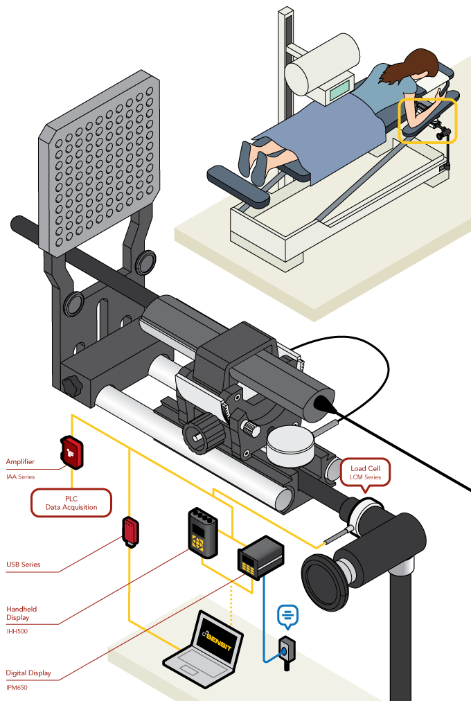
Prone Stereotactic Breast Biopsy
How it Works
- An LCM series Miniature In Line Load Cell is threaded in-line between the biopsy syringe and control arm.
- The output from the load cell is then amplified via the IAA series Analog Amplifier for input into the control system PLC.
- The operator sets the scan location with the computer control system and selects the target for biopsy.
- The system then moves and performs the biopsy while the operator watches to ensure no fault occurs.
- As the biopsy needle is inserted, the load cell reports the insertion force to the PLC allowing the automated system to control entry force to neither be too gentle or too rough.
- Load cell output can also be sent to the operator display for monitoring.
|
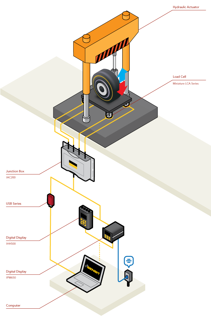
Landing Gear Drop Test
How it Works
- Aviation engineers are required to perform a series of quality and fatigue tests on landing gear.
- Utilizing compressive load cells, these test engineers are able to gauge the load applied to the landing gear during touch down.
- Hydraulic actuators are typically used to perform these quality assurance checks.
- At the base of the platform several Miniature Column Load Cells (LCA Family) are installed. As the actuator propels the landing gear into free fall, these load cells monitor the forces applied to the undercarriage of the aircraft.
- This data can be summed together via FUTEK's IAC200 2–4 Channel Summing Junction Box and then read on either of our digital displays (IHH500 or IPM650) or streamed to our USB Solutions.
- Pairing the FUTEK SENSIT™ Software with this sensing system provides users with the ability to monitor up to 16 channels of measurement, as well as live graph and log data.
|